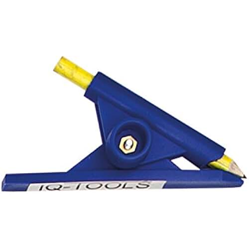

I'd set the scribe / gauge exactly 1/4" above the surface for consistency. Obviously I'd have to verify the long tube is rotated "level" each time I move it along my short table saw depth. I'm wondering if I can't use that on the end of a tube, then lay the tube on my table saw (using the machined miter gauge slot on the top of the table) then use either a machinist height vernier or machinist surface scribe to drag a reference. I happened to be in the hardware store and saw this puppy. ) Unfortunately, the cuts can be slightly out of phase using the tubing manufacturer's black induction welding line reference.
#BACK SMITH METAL SCRIBE SOFTWARE#
(disclaimer: I'm the software developer who wrote that software. Note: In this project I'm making custom shelving brackets, using the round to flat template maker at Those templates include accurate radial references as well as perfect center line length references. I still have to do some filing and grinding to make these pieces fit easily. That appears to be consistent along the length of the tube, kinda sorta. If you look closely at the weld left by the tubing manufacturing process, there is a separation in color. Lately I've been using the discoloration in the metal left by the induction welding process. I tried clamping the angle to smaller tubing, but that's too flaky. This works fine with 1" angle iron with 3" or larger tubing.

I've tried to use angle iron as a reference, with a machinist scribe to place a reference line down the length of the tube. What makes this work is having a reliable reference line that runs along the length of the tube. The paper templates include references so you can coordinate the notching at both ends of the tubing to be aligned radially (in sync). I'm using paper templates at each end of the cut tubing.


 0 kommentar(er)
